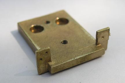
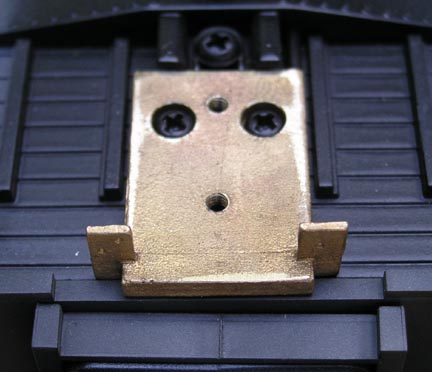
The photos below show the CCP by itself and installed on the car floor using the factory screws. Note the drill spots that are provided for modelers who wish to install for the air, signal, and steam line connections. See 4. below for information on the parts that can be used for the air, signal, and steam connections.
This version is $16.00 per pair plus S&H. Please note that since these parts are produced in batches, there may be a delay in delivery of your order.
Please contact me to discuss availability so a shipping amount can be determined and to discuss payment methods.
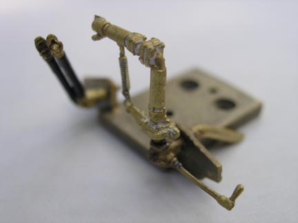
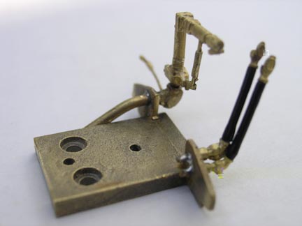
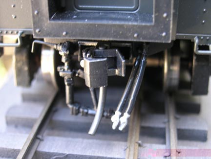
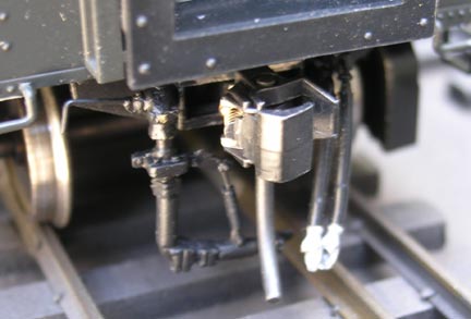
The following two photos show an unpainted CCP that has the air, signal, and steam lines installed.
The following two photos show the painted CCP installed. While not apparent from the camera angle, the KD coupler is located such that when coupled to another KD coupler and one of the cars is not pulling the other, the diaphragms will touch. When one car is pulling the other, a space between the diaphragms of about 3/16" will exist. This is because of the slack action allowed by the KD centering spring. To eliminate this slack action, place a 3/32" diameter rod inside the KD centering spring. The length of the rod limits how much the coupler will pull out of the pocket which is needed on curves because the diaphragms do not flex. I find that a length of .160" allows the cars to get around 60 inch radius curves; the gap between the diaphragms will be about 1/16". Longer rods will reduce the gap and in turn will require larger radius curves. Smaller radius curves will require shorter rods. If you know the length rod you need, I will make them for you for a nominal charge.
The couplers will no longer work for delayed uncoupling if you install the rods. The coupler also will have limited swiveling; this is normally not a problem because there is so much play in the knuckles.
Before installing this version of the CCP, remove the molded-on air and steam line detail on the end near each corner of the car. Flush cutting nippers will remove them quickly. If you wish, clean up the rough surface where the molded-on details were removed with an xacto knife and paint the scar a dark color.
This version is $50.00 per pair plus S&H. Please note that since these parts are produced to order and that I am usually backed up with work, so there may be a delay in delivery of your order.
Please contact me to discuss availability and your shipping preferences so a total amount can be determined and to discuss payment methods.
This is the bare casting. The modeler has to cut off the casting sprue, locate and drill the mounting holes for the KD coupler box, tap the holes 2MM, clean out (if needed) the counter bored CCP mounting holes, and clean up the part by appropriate filing. Tip: the KD mounting holes are located on the center line of the CCP; the first hole is .312" (5/16") from the front face of the CCP, and the second hole is .734" (about 47/64") from the front face of the CCP. Remove the vertical part of the KD coupler box cover to make it easier to mount the coupler box. If desired the modeler can add air, signal, and steam lines as shown above.
This version is $9.00 per pair plus S&H. Please note that since these parts are produced in batches, there may be a delay in delivery of your order.
Please contact me to discuss availability so a shipping amount can be determined and to discuss payment methods.
Note that installing these details requires some filing and fitting, and soldering.
Precision Scale Co. #4649 or BTS Details #12302 parts can be used for the air and signal connections. One package provides enough parts for one car. The advantage of these parts is that the air hose portion is flexible. If the hose connections on adjacent cars collide on curves, the connections will flex rather than possibly causing a derailment. PSC #4649 was used on the examples shown above. PSC 4649 is $5.75 for a package of 4. BTS Details 12302 is $5.25 for a package of 4.
Precision Scale Co. #4049, #40461, or #40462 is the steam connection part. PSC 4049 and 40462 are $9.50 for a pair. PSC 40461 is $9.50 for a pair.
PSC 4049 and 40462 seem to be the same part. The difference between them and the 40461 is that the 40461 comprises 3 pieces per connector - the flexible connection, the steam line, and the shut off handle. Note that the left photo above of the assembled unpainted CCP shows the 40461 with handle that is included with the part, while the right photo above of the assembled unpainted CCP shows the CCP with a fabricated wire rod handle. Also note that the handle shown in the photos is only available in the 40461 part nor is there provision for mounting the handle in either 4049 or 40462 part.
All of the above detail parts are available from me.
Please contact me to discuss availability so a shipping amount can be determined and to discuss payment methods.
Note that price increases by my suppliers occur from time to time. If I have to order parts for you and the price has gone up, I charge the new price, and will let you know before you send money.
- Drilling The Mounting Holes for the KD Box
Note: my standard for couplers is KDs. I have not verified that the Weaver factory coupler can be installed on a fully assembled CCP. If you have trouble with that, please contact me.
The coupler mounting holes are to be drilled #51 and tapped for 2 x 0.4 MM screws. When drilling the hole is it is important to keep the drill vertical to the work; if the holes are tilted, it may not be possible to use both coupler mount screws.
If one or both holes are tilted and both coupler mount screws will not start in the holes, you can either live with one screw which should not present any problems, or locate, drill and tap two holes to accept screws through the mounting bosses on the side of the KD box.
- Drilling the air, signal, and steam line mounting holes.
The sizes below are suggested. Since castings can vary in size from casting to casting, it is a good idea to drill an undersize hole and enlarge it as needed.
The B.T.S. 12302 air/signal hole size is about .035".
The PSC 4649 air/signal hole size is about .040".
The steam line hole in the mounting tab is about .073".
If using the PSC 40461 connector:
- Clean out the hole in the steam line valve body (end of the long casting) where the swivel section (the L-shaped part) of the steam connection mounts with a .052" drill. The valve body must be fixed in place (held in a machinist's vise) for best results.
- Make the hole where the shutoff handle mounts in the valve body with a 000 center drill. The valve body must be fixed in place (held in a machinist's vise) for best results.
- Suggested Assembly Sequence
First solder the steam line in place, butting it up against the mounting tab. Then solder the air/signal lines in place. Then solder the steam connection swivel in place. Lastly, solder the control handle in place. Properly used resistance soldering equipment works well for this work.
Clean and paint. Paint the air/signal hose glad hands a medium gray color, or a special color if your road used that color.
A suggested length for the air hose (top hose looking down towards the rail) is 15/32". A suggested length for the signal hose is 7/16".
Remove burrs from the nipples on the glad hands and hose control valves. Insert the glad hand into the hose, then the hose onto the control valve nipple.
- Tips on Assembling the CCP to the Car
On some of these cars the floor is recessed into the car body such that the end protrudes above the floor. If the CCP is allowed to rest on this lip rather than being pressed down towards the center of the car where it will snap in place on the floor, the CCP will be tilted causing the coupler to tilt. To prevent this from happening, place the CCP on the car floor so that the tabs on the front are behind the end wall of the car. While keeping pressure on the front the the CCP, insert the mounting screws and tighten them until the CCP snaps in place. Push the factory-supplied steam line towards the center of the car if it is in the way. Sight towards the end of the car and verify that the coupler is not tilted down. If it is, remove the CCP and start over again being more careful this time.
Before proceeding further be sure to read the comments above about placing rods inside the KD centering spring.
Assemble the KD coupler and box. Getting the coupler box in place on a CCP that has the steam line installed might take some fiddling but be patient. I found that it helps to pull the coupler out of the box (against the centering spring) while manuvering the box into position. If you have installed rods inside the KD spring so that the coupler won't pull out of its box very far, another approach is needed: pull the flexible hoses to one side and then lower the KD box through the opening and slowly rotate it from being on its side to being "bottom up" as it approaches the car floor.
- Coupler Height
The cars came from Weaver with 36 inch diameter wheels. The correct diameter is 33 inches. Keil Line offers a replacement bolster that narrows the over-wide trucks and that provides for smaller diameter wheelsets. Please contact Keil Line for more information.
The larger diameter wheels make the car sit slightly (.015") high. The CCP is designed for 33 inch wheelsets. If you install the CCP without changing wheelsets the coupler will be on the high side. If this becomes an operational issue and you don't want to change the wheelsets, just install a shim above the coupler so that it will sit lower.