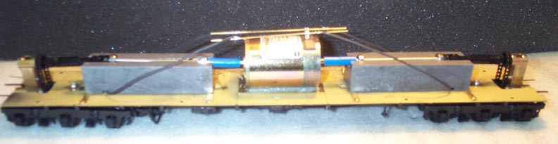
The gear ratio is 7.5:1 which produces a top speed of 65 scale MPH at 12 volts.
I fabricated everything other than the obvious purchased items. Many of the purchased items were modified to fit or to suit their task or to increase their reliability. Other items, such as the weights, were machined to fit and/or to suit their task.
The motor is glued to its 1/32 sheet brass mounting bracket using silicone sealant. You can pick up a heavy loco by the motor, the bond is so strong.
All photos were taken before the gearbox, et al were painted black.
I use Weaver sliding U-joints to connect pivoting shafts with fixed shafts. Depending upon the problem being solved, certain u-joint "helmets" and chain sprockets are pinned to their shafts. You can see the pin in the helmet that is directly in front of the ball bearing near the end of the weight.
The weight is secured using a brass strip at each end. Two screws through the brass strip attach it to the weight. The strip is then screwed to the floor. Note the notch cut in the weight to clear the wires from the trucks to the motor.
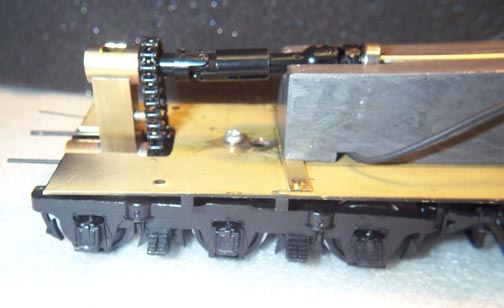
You can see in this photo and the next where the truck mounting point
was moved to the truck
center. That way the weight on the truck is distributed equally to all axles.
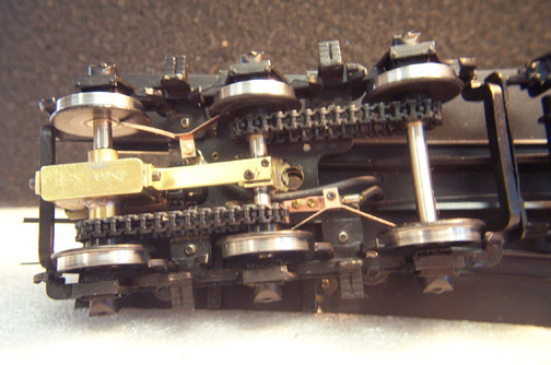
Here is a bottom view of the truck. Visible are the phosphor-bronze pickup wipers. Using all three of the photos for this job, you can trace the wiring from the wire lug on the bottom of the wiper mount to the motor brush buss bar. The car has 8-wheel pickup.
The sprockets are not press-fitted to the axles, which will cause them to split eventually (raise your hand if you have had a loco with a split plastic gear - my hand is up!) Instead I ream the sprocket hole to be a slip fit onto a brass bushing (the reaming also reduces the run-out of of the molded sprocket.) The bushing is knurled so that when the sprocket is pushed onto it, the raised edges of the knurls cut into the plastic and grip it, preventing the sprocket from turning on the bushing. The bushing is then press fit in a metal-to-metal fit onto the axle shaft. You can see the bushing in the sprocket on the middle axle.
Barely visible on the bottom of the gearbox is the stamped code "RM 34". The RM identifies the drive as mine, and 34 is the drive serial number.