Page Originated 8/1997
Page Updated 06/13/2022
Last update:
MAKING YOUR LOCOS LOOK AND
RUN THE WAY YOU WANT
GEAR BOX GUIDED TOUR
GEAR BOX GUIDED TOUR
Thank you for visiting!
This page provides a guided tour of the gearboxes I fabricate. My apologies for the quality of some of the photos; I will replace them with brighter and clearer ones as soon as possible.
My gearboxes comprise a phenolic worm gear, a brass worm, and brass sheet and tube.
I fabricate the worm gears from 1/4" thick phenolic sheet, the worms from 3/8 dia. solid brass rod,
the gearbox sides from 1/32" thick brass sheet, the worm tube from 1/32" wall
brass tube, and the side extension tubes from 9/32" solid brass rod.
The worm gear is 32DP 30 teeth 1" diameter, the worm is of course also
32DP and 3/8" diameter. With a single tooth worm the ratio is 30:1, with
a two tooth worm, the ratio is 15:1.
The fabrication sequence is as follows:
-
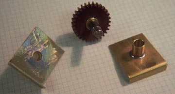
A heavily knurled bushing is pressed into the one inch diameter axle gear. The
bushing is bored to be a press fit on the axle. The combination of the knurling
on the gear and the metal to metal press fit of the bushing on the axle assures the gear
will cannot slip.
Each gearbox consists of a pair of halves that are soldered together to
create a box with narrow openings at both the top and bottom. The worm
shaft assembly is fitted to the top; the bottom is covered with a plate
that is stamped with "RM xxx" where xxx is the custom drive's serial
number.
Note the stabilizer tubes on each side of the gearbox, which are unique
to this design. The tubes eliminate the gearbox's squirming on the
axle. Run one of your locos upside down and chances are you will see
the gearbox squirming. With my design all the energy put into the
gearbox goes into turning the axle, and no place else.
-
Some important things to know about worms and worm gears:
The worm's tooth (or teeth if the worm is a multiple lead
worm) pushes or pulls (depending upon the worm shaft rotation)
the worm gear as the worm turns. Since
the worm is fixed in position longitudinally but the worm gear is free
to rotate, the worm gear turns, turning the axle and the wheels.
However, as the worm gear turns, its (the train's) resistance to being
moved causes the worm gear to tend to push or pull the worm depending
upon the locomotive's direction.
This force upon the worm shaft is called end thrust. If the worm shaft is rigidly connected
to (or is part of) the motor shaft, then the motor shaft is subjected
to end thrust too.
The reason some locos run better in one direction than the other is
that end thrust on the motor shaft in one direction allows the motor to
run better than it does when the end thrust is in the opposite
direction.
The best way to fix the worm in position so that there
is no back and forth movement of the worm shaft is to use ball
bearings, which efficiently absorb the end thrust caused by the
resistance of the worm gear to being turned.
The distance from the center of the
axle to the contact point of the worm tooth and the worm gear tooth is
a lever arm. The longer the lever arm, e.g., the larger diameter the
worm gear, the less work it takes to turn the worm gear.
The diameter of the worm is also a lever. Consider loosening a screw
with a small diameter handled screwdriver then switching to a large diameter handled screwdriver.
-
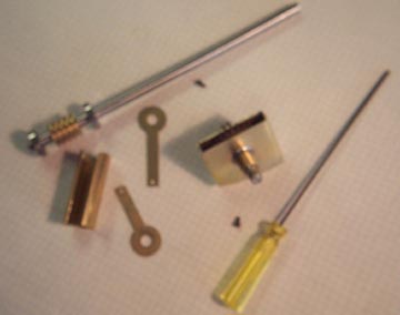
The gear box is totally enclosed. In the photo below you see the
assembled gearbox, the worm shaft assembly, the tubular worm housing,
and the gearbox end pieces. The end pieces are soldered onto the end of
the worm housing and serve to fix the worm shaft to the gearbox by
screws that enter the gearbox from the side at the bottom of each end
piece. Note that the forces that push the worm away from the worm gear
are shear forces on the shafts of the screws, rather than shear forces
on the threads of the screws that retain the bottom on conventional
gearboxes. Those screws are socket head screws and are shown in the
photo. The yellow handled
hex head ball driver shown will drive the screws from an angle making
it easy to remove (and to later replace)
a screw for lubrication when the gearbox is installed
in the loco. It is included with every custom drive.
-
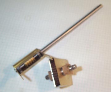
The loco's axle bearings are modified for a tight slip fit on the
gearbox's axle tubes. The worm housing and end pieces are soldered
together. The serialized gearbox bottom plate is soldered in place.
Excess solder is removed. Note that the worm shaft is custom made to a
length such that there is 1/32" between its end and the end of the
motor shaft. With such a gap, a piece of tight gripping but flexible
tubing provides a simple reliable absolutely silent connection between
the two shafts that has no moving parts.
-
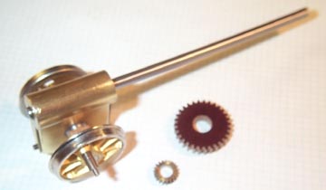
Finally, the wheels are installed and the gearbox is complete. At this
point the gearbox is installed in the loco, the side rods are
installed, and the mechanism is run in on the bench.
The assembled completed
loco is broken in and thoroughly tested while running continuously -
compare to back and forth on three feet of track.
To highlight the differences in the diameters with some factory worm gears
compared to my worm gear I have shown an extreme example of a factory worm
gear; recall the comment above about lever arms.
Interested in learning more about 2-rail O scale? Please visit the O Scale Kings web pages.
These web pages were designed and implemented by Rod Miller.
© 1998-2025 Rod Miller All Rights Reserved